Creating a customization menu in Blender
This section is aimed at any model maker that might want to make their own customize menu in Blender, as I do want it to become a standard for more complicated models that have a lot of options, and for model makers that want their models to be more optimized.
I know it might seem really, really complicated, but it’s not that much different from how animator layers work in Unity. Once you’re used to this menu, you’ll hopefully see the way it saves time.
Custom Properties
Just like in Unity, we have Parameters in Blender, they're just called "Custom Properties". The difference is that in Blender, Parameters are tied to things like objects or bones. For some of my projects, these might be on the armature tab, or the menu bone.
Note
For animation rigs, it's very common to put these properties on a bone, as it makes more sense when animating these properties. I put these on the armature itself sometimes which is a bit unconventional.
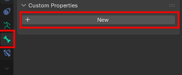
There's integers, Floats and bools, which you should be familiar with. You can even set the maximum, minimum, and default value! You should probably create a bone dedicated to these custom properties then in pose mode, navigate to the bone tab and click “new” under Custom Properties. Your parameter will then be tied to that bone.
Warning
Make sure to put this property on a bone while in POSE MODE, adding it on a bone in edit mode means it'll only be accessible in edit mode, which is less desirable for animation.
Note
When creating parameters, you need to CLICK “ok” when you're done, or else your settings will be discarded.
Drivers
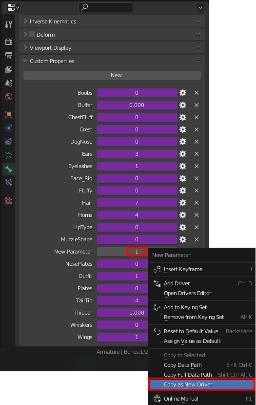
You can use that parameter to change almost anything in the Blender file! All you need to do is right click the parameter’s value and click “Copy as new driver”
“What is a driver?”
Drivers in Blender are like links between values. Think of them like transition conditions in Unity’s animator layers, or even something that can control a blend tree.
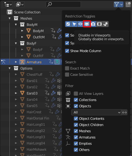
For this example, we’ll use the “disable in viewport” option. Make sure the option is visible using this filter! It's usually off by default.
Next, we right click on the viewport visibility for the object we want to control and paste the driver. For this instance, we’ll use “ChestFluff”.
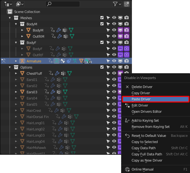
You’ll notice that once you paste the driver, it turns purple. Great! You won’t be able to manually change the value anymore, but You can still hide it using the eye icon. Now that that’s done, we can begin to edit the driver by right clicking it and clicking “Edit Driver”
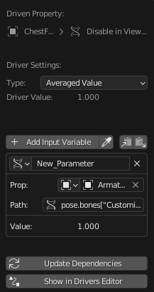
In this example, we'll use a scripted expression, not an averaged value. This is usually the case if you need to control a toggle or blendshape with multiple conditions, but average value can be used if the toggle is very simple.
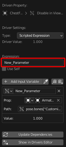
You’ll see this new box appear. This is where the magic happens. Technically, this is scripting in python, but you don’t need to learn the entirety of Python to use it! It’s really just like Unity conditions, just formatted slightly differently.
First, you need to think about which value gives the effect that you want. It tends to be either 0 or 1. “0” for viewport visibility means that it is visible. 1 means it is hidden. (weird, I know.)
so we first tell it we want our object to be visible (0) when New_Parameter is set to 1.
0 if New_Parameter == 1
great! but it’s not over. we need to tell it what to do when New_Parameter is not set to 1.
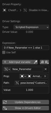
0 if New_Parameter == 1 else 1
Think of it like saying “set it to visible (0) if our parameter equals 1, otherwise hide it (1)”. It might be a little weird to get used to, but it won’t get that much more complicated.
Python has a few different statements you can use. == for equals to, != for NOT equals to, bigger than (>=), smaller than (<=), etc. You can also use “and” and “or” statements, but make sure to reiterate which parameter you are referring to after using these statements. For example:
0 if New_Parameter == 1 or New_Parameter == 2 else 1
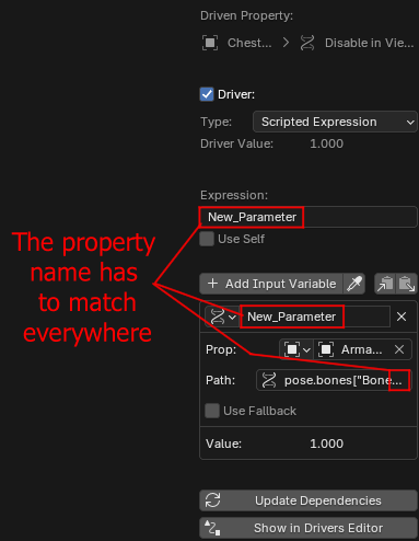
Warning
Property names have to match in all 3 boxes! The name of the property is also at the end of the "Path" section.
Now that we have our toggle, and it turns visibility on or off, we can test it by going back to pose mode and looking at the custom property on the bone we chose for it. setting it to 1 should make it visible. Setting it to 0 should hide it.
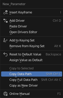
You can use multiple variables, but in order for Blender to use them, you need to tell it where that variable is located. This is where the “path” comes in. You can copy the path of a variable by right clicking that parameter and clicking “copy data path” then pasting it in the “path” section of the driver.
You can also bulk copy variables of a driver and paste them somewhere else with the clipboard icon above the variables section.
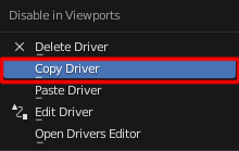
Normally, if you want something to be hidden in the viewport, you usually want it to be hidden in the render view. Thankfully you don’t have to make the same driver over again. you can right click the driver and copy it, then paste it onto the “disable in renders” function.
You can make it drive Object visibility, Render visibility, but also Blendshapes, Bone layer visibility, and most importantly, the Deform value of certain bones.
“Why would I want to use a driver to toggle the deform value of a bone?”
This is a little situational. Having a lot of bones that are unused on your VRChat avatar is not exactly optimal. For tthe Drakonoid for instance, I have a few different hairstyles. having all of the bones active for each hairstyle means a lot of them go unused. So, I toggle the deform value to off using a driver when the hairstyle it’s used with is not visible. Because of the export settings I showed, only bones with their deform value set to “on” are exported, and so unused bones are discarded on export. Unfortunately, If you want to drive the deform value of a bone, you’ll have to copy and paste a driver on every affected bone. Like, manually.
Other notes
In the previous example, we've SET the property's value to 1 or 0, but we can change the value in a few different ways.
Property_1 if Property_2 == 2 else 0
Putting a property name instead of a number will instead use the Property's curve to determine the value. In order to understand this, we have to explain the driver editor.
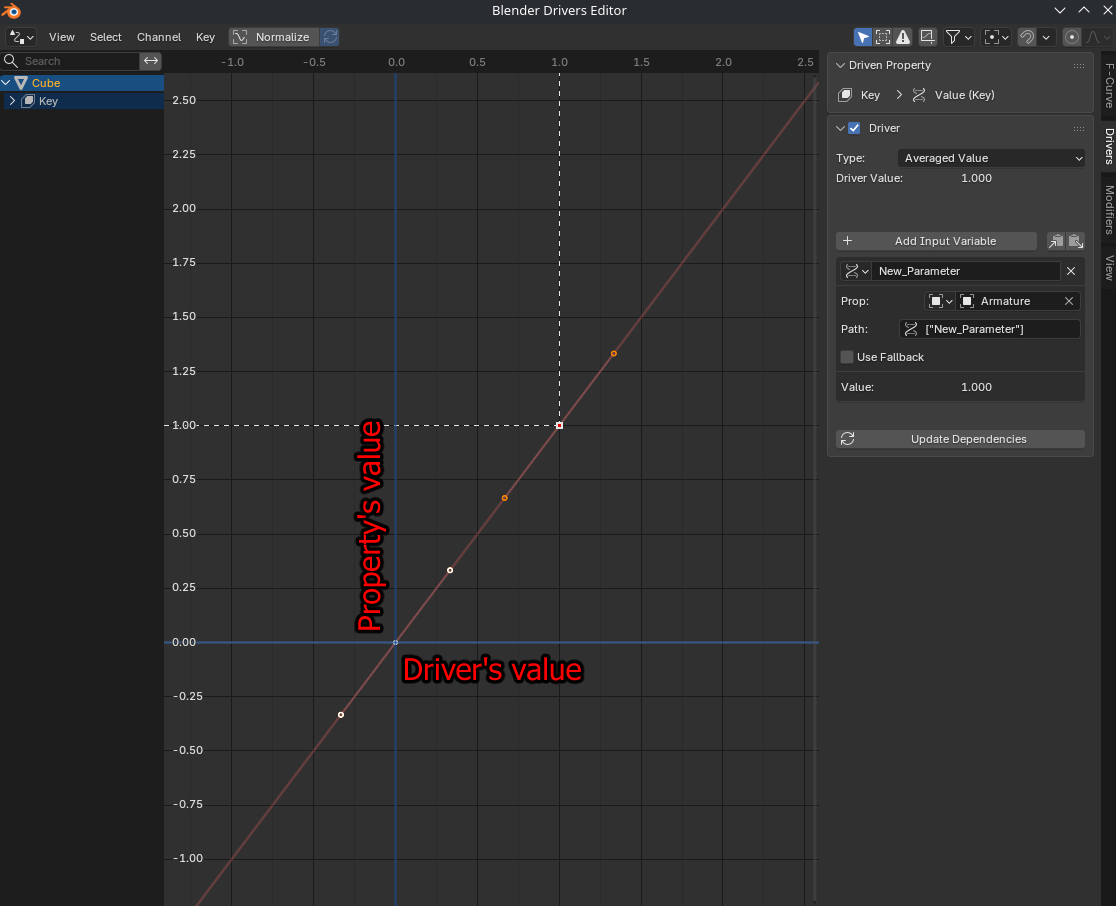
The driver editor is a bit hard to wrap your head around, but it is essential to learn. What you need to understand is that the value of the driver and the value of the Property are somewhat decoupled. The driver only controls the X axis on the graph, while the Y axis is what value the property will be at that spot.
If the driver sets the property to 1, by default, the end result of the value will be 1, but you can move, add or remove the "keys" which are the little dots on the graph, so that the end result can be 2, or 0.5, or whichever value you want. This can be useful for making a rig's UI for instance, where a bone's location needs to drive a value to 1 without travelling 1 meter across.
Issues with using one float for multiple "states"
If you have a property with multiple "states", for example a breast slider, where you may have a "pectoral", "smaller", default, or "bigger" state on the same slider, I strongly advise to make separate parameters for each of those states that each transition between 0 and 1 based on a "main" property (like breast size).
While the driver editor is a powerful tool, having this decoupled driver value and parameter value can create awkward situations.
Let's once again use a breast slider as an example. You might have a pectorals blendshape gradually increase to 1 when the Breast_Size property reaches 0, which seems fine on the surface, but say that you have a corrective blendshape that blends to 1 when both chubby and pectoral states are on? Normally, like in a blendtree, you'd simply multiply Breast_size by the Chubby parameter.
Unfortunately, doing this introduces complications, because using our curve, our pecs blendshape gradually increases to 1 near 0. What happens if we multiply the Breast_Size parameter with the Chubby parameter?
Assuming they're both 0, then pecs are active, but chubby isn't, which means the result on the driver is 0. What value is the property when the driver is 0? ...it's 1, which is not the desired value under those conditions.
Which is why it's much simpler to just create a few extra parameters that simply go from 0 to 1, and using the existing Breast_Size parameter as a driver, we can make it drive a "pectoral" parameter to 1. That way, if you need a corrective blendshape to blend to 1 with chubby and pectorals, you only have to multiply them together. Because pecs is going to 1 when active instead of 0, you'll get the correct result. I hope this makes sense. I know it's a lot to take in.
The Menu
Making a menu is a little tricky, and kind of optional since one can just change the parameters directly on the armature you made, but it makes it slightly easier to work with for people who don’t know about parameters.
You can make a menu and knobs like mine using custom shapes. What this means is that you can use planes (without the faces) and edges and just build sliders out of simple shapes. I heavily rely on the grid that’s on the ground to make it easier on myself. You can use the text tool and convert it to mesh, then merge it with the menu. Don’t make the knobs on the same object, though! that will be used by another bone.
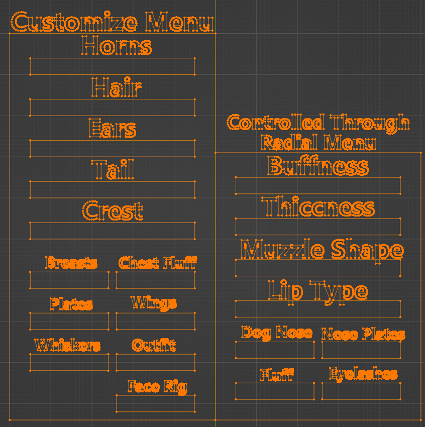
Once it’s done, you can give a bone that appearance by clicking a bone in pose mode, going to bone properties and viewport display.
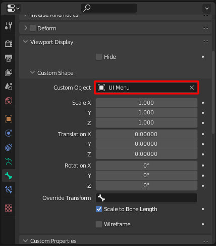
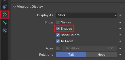
Do note that the Custom Shape might not show up by default, and you might need to check “Shapes” in the armature tab for it to show up.
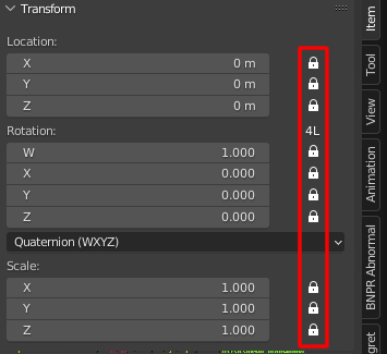
You should then lock all of its transform values so that the menu can’t move.
For the knobs, It’s the same process for making them, but each knob is another bone that is a child of the menu bone. You can try and place it at the start of the slider in edit mode. Use the grid to make it match the slider as much as you can. You can change the scale of the knobs from the custom shape menu, but I wouldn’t mess with the location of them. Be aware that a bone’s length determines the menu and knob size. Try to keep the length of the bone a round number. You can also change the scale of the bones in the bone tab, but it’s good to be consistent.
Once a knob is properly placed, you can lock all of its values except for the X location.
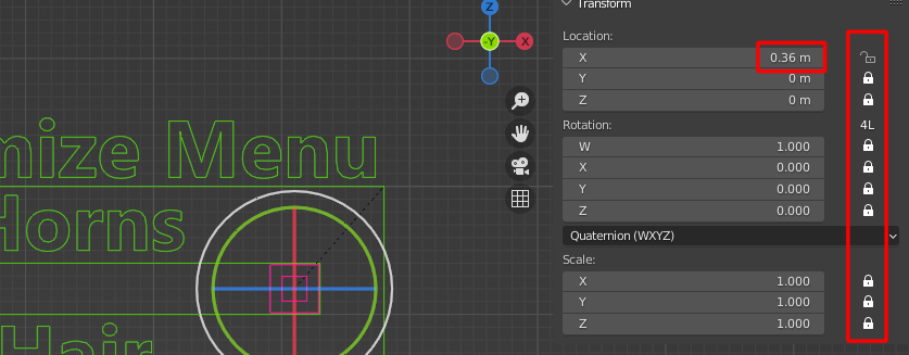
While we’re at it, bring the knob to the end of the slider, and take note of where it rests in the X location. in this case, it’s 0.36 m
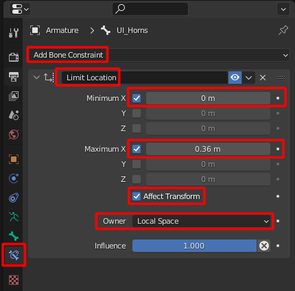
Add a limit location constraint, set its minimum x to 0 and its maximum x to the value it was at the end of the slider. we also want it to affect transform, otherwise the x value will keep increasing past the limit, and will only visually stay at the limit. Set the owner to local space, so that it actually starts at 0.
Now, it’s time to make a driver drive a driver.
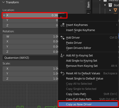
Right click and copy the x location of the knob as a new driver.
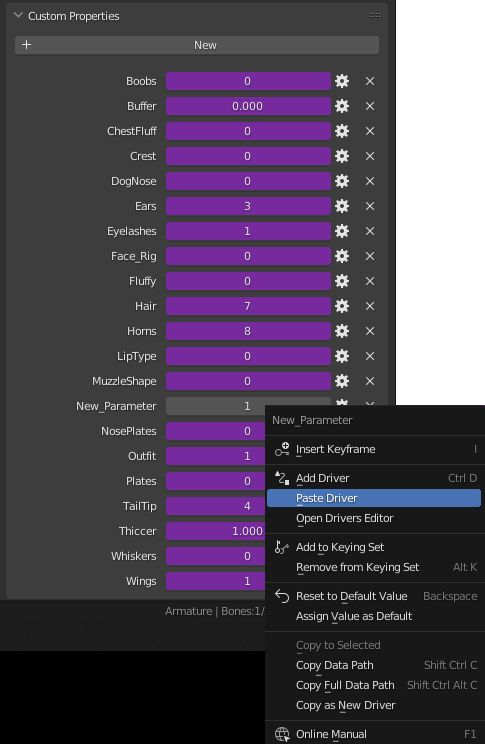
Then paste it onto the Parameter we created. This time, instead of making a scripted expression, we’ll play with the drivers editor.
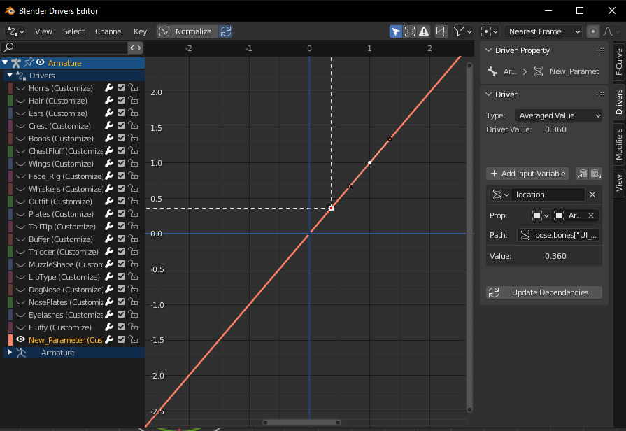
Ignoring all of my other parameters, you’ll end up with this graph. Now, because the x location value of our knob at the end of the slider isn’t 1 but instead 0.360, we’ll need to move that white dot higher so that when the knob is at the end of the slider, the value is 1. If your parameter goes higher than 1, then you might need to move it a lot higher. The important part is that when the slider is at the end, it does what you want it to do. You can just leave the knob at the end of the slider and move this dot until it gives you the result you want. A better way to do this would be to use the F curve tab on the right to move it exactly where you want. You can move it left or right too instead of just up or down.
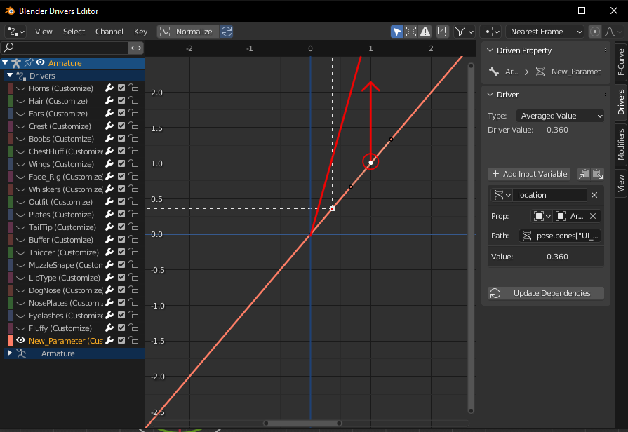
And that’s it! you should have a working knob that controls your parameter. You can repeat the process for every slider you want to make.
If you want to have custom colors for your menu, you can change it in the viewport display section of the bone. You can then copy the color over by selecting all the bones you want and choosing the colored one last, then use the copy feature.
This should cover just about everything. Don’t be afraid to look at the drivers I made to try and understand them.